
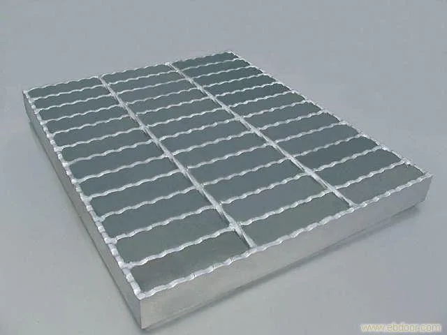
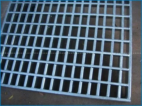
This article focuses on grating stair treads and covers three parts in order: points to note during fabrication, the position of side bolt holes, and basic concepts, with practical advice added after each section. If you are comparing options or preparing a purchase, check the points in order; the section on steel stair treads can be verified against the same list, and any mismatch with site conditions should be adjusted accordingly.
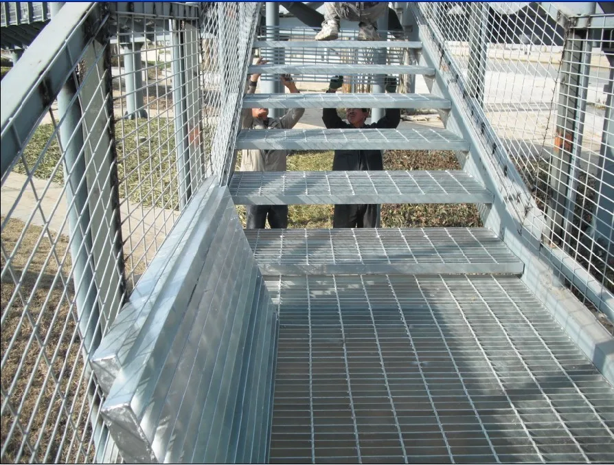
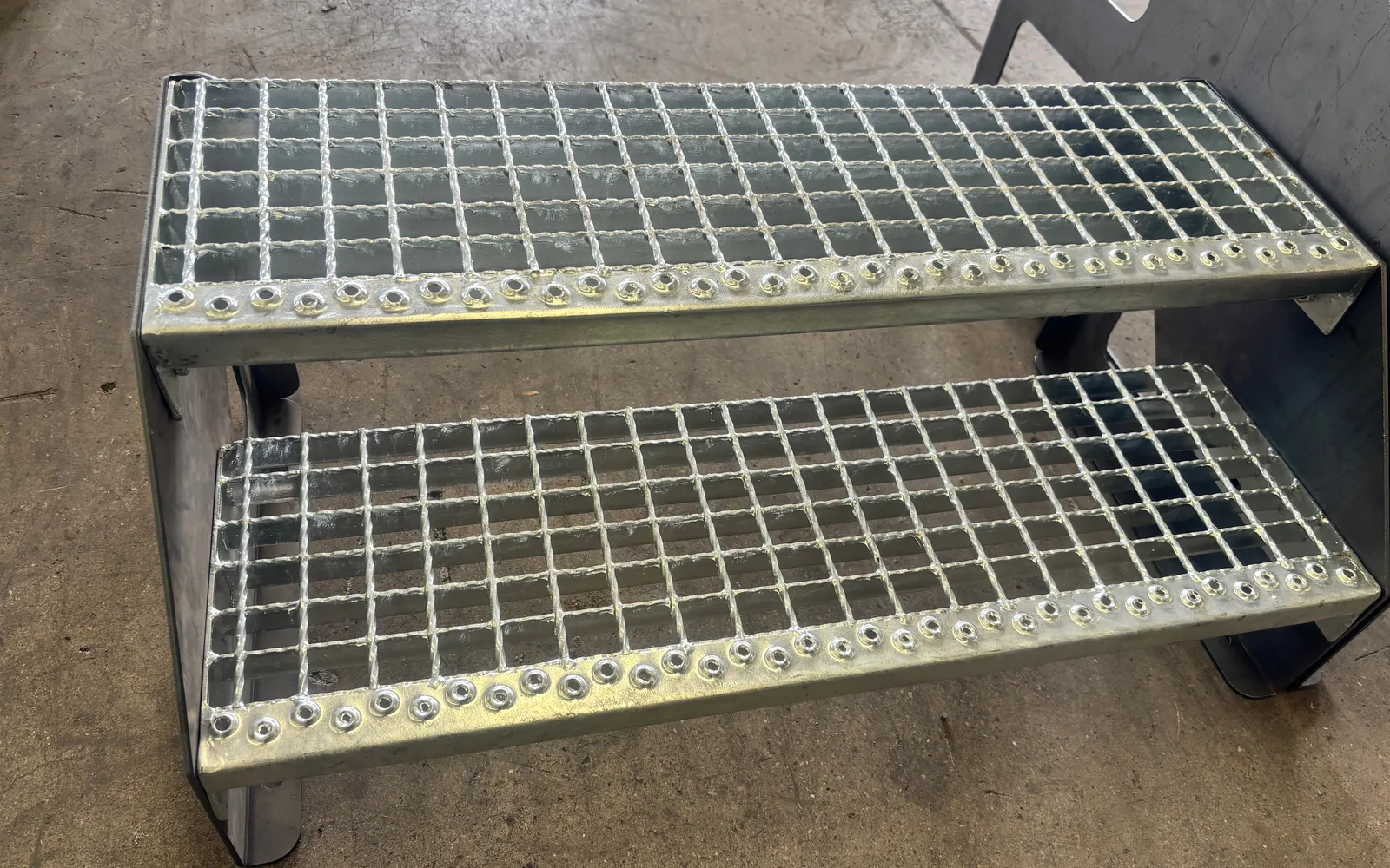
Steel grating stair treads, especially T4 standard stair treads, are widely used and offer advantages such as simple installation and slip resistance,
but the following points should be noted during fabrication
Typical production steps and control points are as follows:
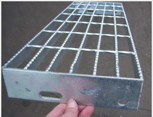
Only when control points of each process are implemented can dimensional accuracy and appearance quality of finished products be guaranteed.
A practical tip for specification confirmation: list the flat bar size, bearing bar pitch, cross bar pitch and overall dimensions together on the purchase order. Listing only one or two of them often results in a delivery mismatch. The full specification notation for grating stair treads is given on the product page; number each tread against the layout drawing before ordering, and the same applies to welded steel grating.
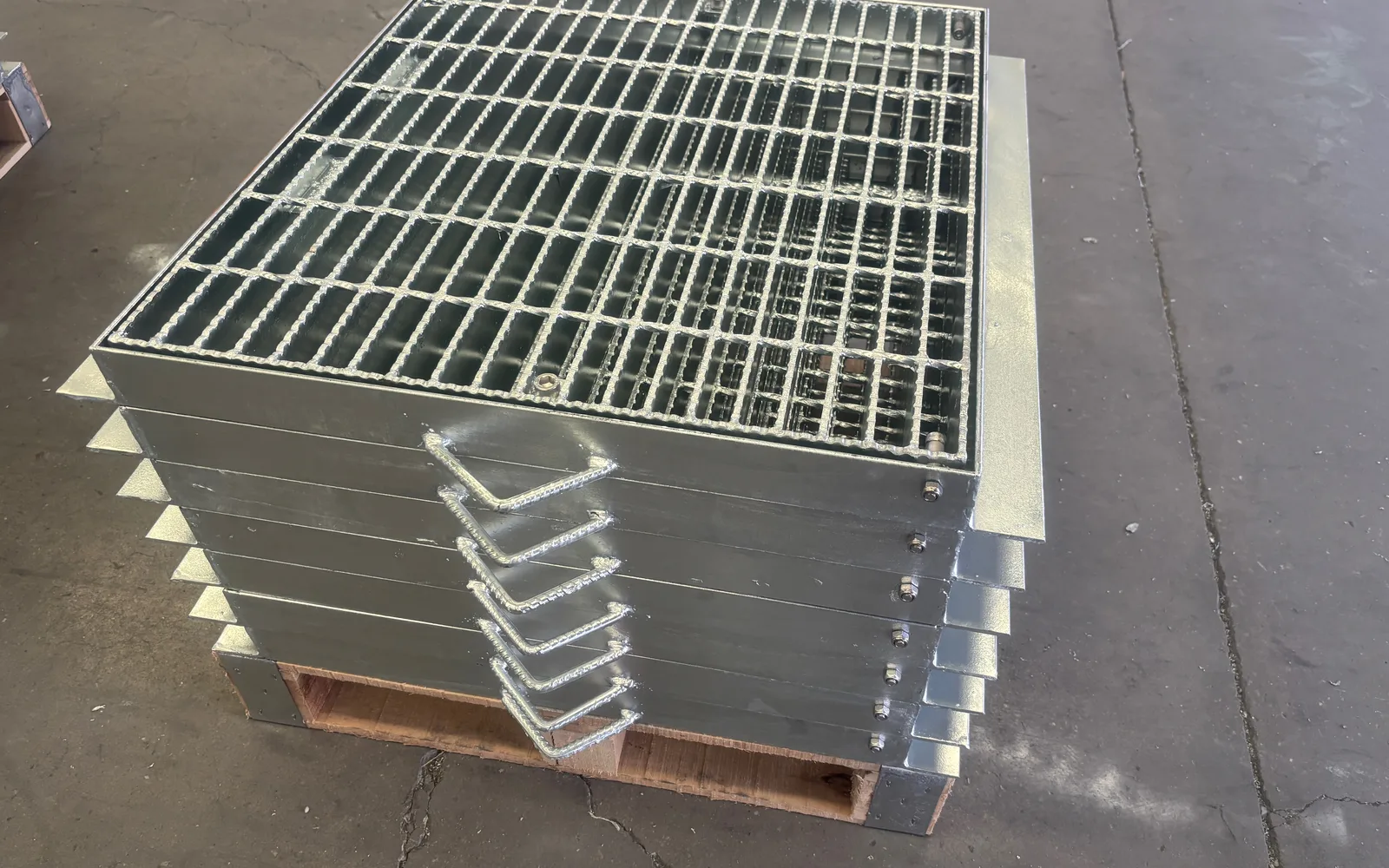
1. The bolt hole positions on both side edges must correspond to the supporting side beams.
Key points for construction and fixing are as follows:
2 Both side edges need corner cuts, otherwise the appearance and overall installation are affected.
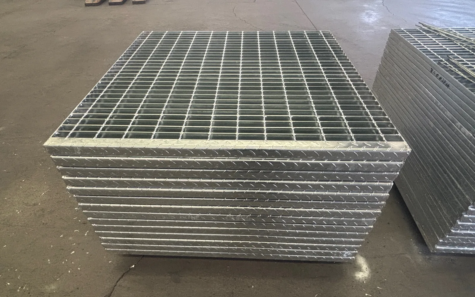
3 When manufacturing stair treads from steel grating, consider the position of the cross bars so that they line up in a straight line from top to bottom after installation.
After installation, check each panel's fixing points and flatness; put into use only after confirming no warping or looseness.
The installation quality of grating stair treads depends largely on preparation: whether the bearing surface is level, whether beam spacing matches the layout, and whether fasteners are ready in advance. With these in place, installation itself is straightforward. If cutting is required on site, the cut-edge treatment for steel stair treads should also be specified.
4. Welding of checkered plate and points to note for use, to be continued
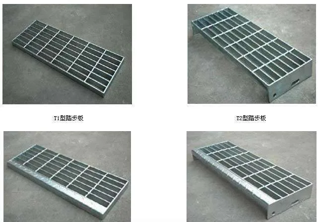
Recommended width < 215 235 245 >
Length 600 800 1200mm Type 255/30/100 325/30/100
From order to delivery, the main intermediate steps for grating stair treads are layout confirmation and surface treatment, both of which take a fairly fixed amount of time. If the schedule is tight, confirm the layout drawing first so that production of welded steel grating can proceed in parallel.
Further Reading: Selection Points for Steel Stair Treads and Welded Steel Grating
If a project uses both steel stair treads and welded steel grating, it is advisable to plan them on the same layout drawing. This allows edge trimming, fixing and cut-outs at the interfaces to be handled uniformly, avoids dimensional conflicts during installation, and simplifies later maintenance.
- For all product specifications and theoretical weights by series, visit Steel Grating Product Center
- To estimate cost by size and quantity, use Instant Quote PageSubmit Requirements
- To see how similar projects were executed, refer to Project Cases field applications
FAQ
Why do different manufacturers quote different weights for the same specifications?
The main difference lies in the actual measured thickness and tolerance control of the bearing bars. When bars are supplied at the lower tolerance limit, weight per unit area falls below the theoretical value, and load capacity drops accordingly. We recommend specifying thickness tolerance clearly when purchasing.
Where can I find specific specifications?
our websiteProductsCommon specifications and theoretical weights are organized by series, also available in Instant Quote PageEstimate by size, or contact us directly for sizing advice.
Can the values in the article be applied directly?
Values in this article come from relevant standard clauses or common industry practice. For actual selection, recalculate based on site span, load class and service environment; direct copying is not recommended.
The above is for sizing and construction reference. To verify specific parameters or request a quotation, please visitInstant Quote Page, or contact our technical staff.
Note that this article presents sizing approaches and general practice, and does not constitute a strength commitment for any specific project. For load-bearing safety-critical areas, the design drawings and on-site calculations shall prevail; contact our technical staff if in doubt.