01Scope and Limitations
1.1Applicable scope
This criterion applies to light-duty steel grating formed by welding (press-welding) of bearing flat bars and cross barslight-duty steel grating, used where pedestrian traffic and very light pneumatic rubber tires roll, including handcarts, flat trolleys, two-wheel hand trucks and cleaning carts.
Typical applicable locations
- Pedestrian walkways, operating platforms, inspection access ways
- Stair Treads
- Trench covers / pit covers (pedestrian crossing)
- Standing areas during equipment inspection and maintenance
- Traffic surfaces for handcarts, flat trolleys and luggage carts
Not applicable (separate design required)
- Forklifts, clamp trucks, stackers and other solid-tire vehicles
- Road vehicles such as cars and trucks
- Support of dynamic equipment such as cranes and winches
- Areas subject to significant impact, vibration or repeated fatigue
- Concentrated support points serving as equipment foundations or pipe supports
The light/heavy series are distinguished by the way wheel pressure acts, not by load magnitude. Solid-tire vehicles concentrate large weights on tiny contact areas, causing local buckling, web crushing and impact effects on bearing bars - a stress state that cannot be described by simplifying the grating as a bending beam. Therefore, even if the bending check passes, the light-duty series must not be used for forklift traffic.
1.2Service conditions
- The grating is arranged as single-span simply supported, resting on support beams at both ends; supports carry no negative moment.
- Bearing bars are perpendicular to the support beams; the span L is taken as the clear distance.
- Ambient temperature is within the normal service range for steel, with no significant corrosion thinning; reductions should be applied separately for corrosive or high-temperature conditions.
- Loads are static; this criterion does not include impact factors or fatigue checks.
02Symbols and Units
| Symbol | Name | Unit | Description |
|---|---|---|---|
| U | Uniformly Distributed Load | kN/m2 | Load distributed over the full panel surface |
| C | Concentrated Load | kN/m | acting at midspan, converted by per meter of panel widthinto a linear load |
| S | Section Modulus | cm³/m | Sum of section moduli of bearing bars per meter of panel width |
| I | Moment of Inertia | cm⁴/m | Sum of moments of inertia of bearing bars per meter of panel width |
| L | Simply supported clear span | m | Distance between the inner faces of the two supports |
| D | Deflection | mm | Maximum vertical deflection at midspan |
| E | Modulus of Elasticity | MPa | See Chapter 3 |
| F | Allowable bending stress | MPa | Safety margin already included; see Chapter 3 |
| M | Bending capacity | kN·m/m | Bending moment that can be resisted per meter of panel width |
Table 1 Symbols used in this criterion. Where S, I, M, C are all "per meter of panel width" values; the panel width, as a common denominator, cancels out in calculation and is independent of the strip width chosen.
S, I Product catalog or measured values should be used preferentially. For geometric estimates, use the following formulas (counting bearing bars only, excluding cross bar contribution; results are on the safe side):
03Material Design Parameters
| Material | Modulus of elasticity E (MPa) | Allowable bending stress F (MPa) |
|---|---|---|
| Carbon steel | 2.0×10⁵ | 124.1 |
| Stainless steel 304 / 316 | 1.93×10⁵ | 137.9 |
Table 2 Material design parameters. Stainless steel has about 3.5% lower elastic modulus than carbon steel but about 11% higher allowable stress; stainless steel is advantageous for short spans governed by strength, while carbon steel is slightly better for long spans governed by stiffness.
F is an allowable bending stress that already includes the safety margin, so the value obtained directly from Eq. (1) M is the allowable bending moment; during calculation do not multiply or divide by safety factors again. This value is not the design strength of steel f (e.g., 215 MPa for Q235); the two differ by about 1.7 times and belong to different design systems, so they must not be substituted for each other.
04Calculation Model and Basic Assumptions
Take a strip of unit panel width (1 m) as the calculation element, simplified as a single-span simply supported beam: the span is the clear span of the grating L, and the section properties are those of all bearing bars within the strip width ( S and I). Loads are uniformly distributed along the panel width, hence measured "per meter of panel width".
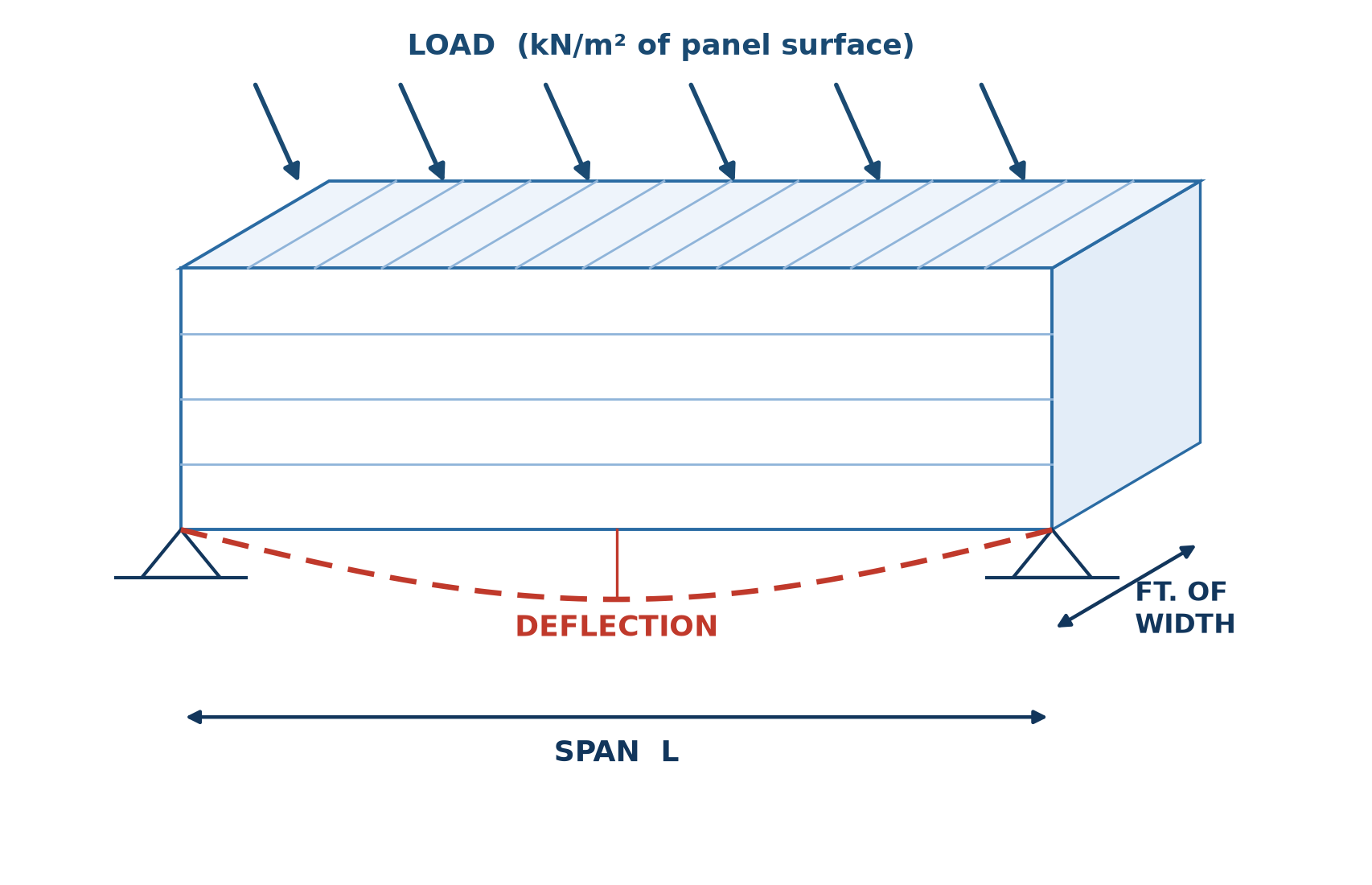
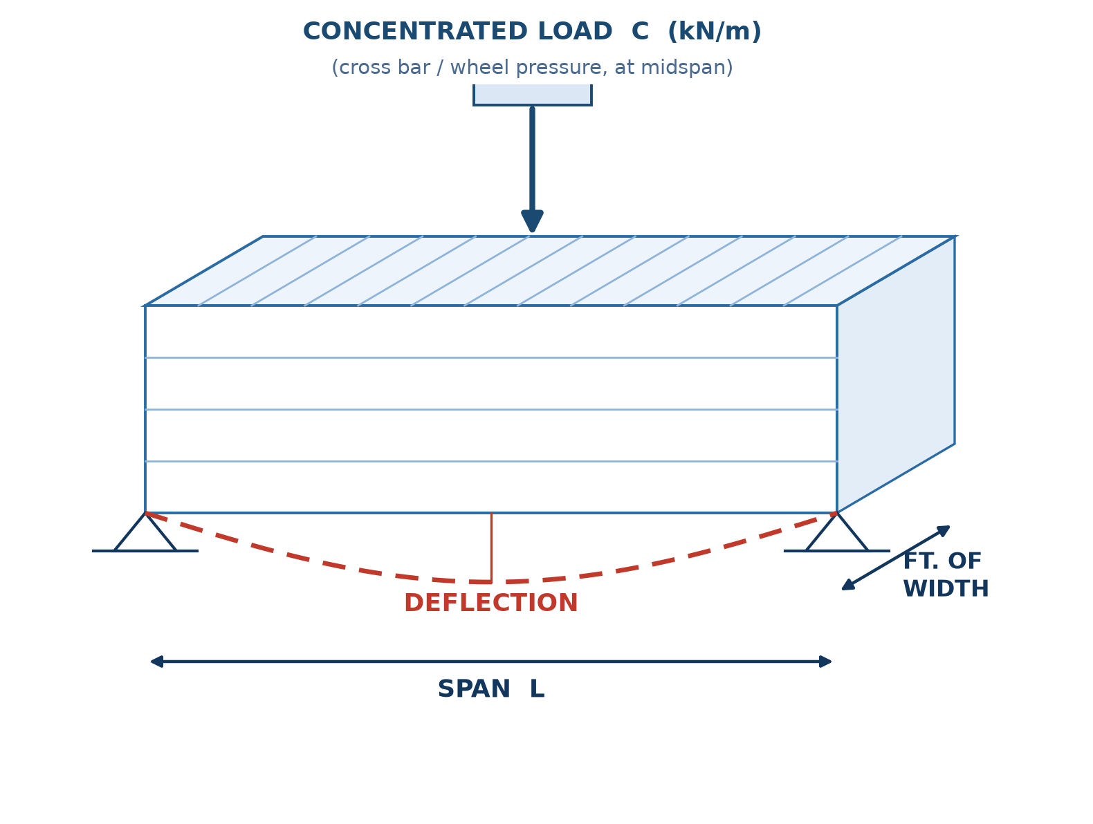
Under the above simplification, the mechanical diagrams of the two cases are shown in Figure 3.
Figure 3 Mechanical diagrams of the unit-width strip beam: a for uniform load over the full width, b for concentrated load at midspan; L is the simply supported clear span, D is the midspan deflection.
4.1Basic Assumptions
- Single-span simply supported. Resting on both ends without rotational restraint; when actually welded or fixed at multiple points, support restraint redistributes internal forces, so the simply supported assumption is on the safe side.
- Only bearing bars bend. The bending contribution of cross bars (twisted square bars) is not counted; they serve only as lateral ties, so S, I is underestimated and the result is on the safe side.
- Loads are averaged over the panel width. Concentrated Load C is the line load converted per panel width; actual wheel pressures and leg loads should be converted to kN/m by contact size.
- Static calculation. Impact, braking forces and fatigue effects are not included.
- No local stability check. Bar height-to-thickness ratio, local web buckling and local bearing at supports should be ensured separately by detailing and product standards.
05Load Capacity Calculation Method
Follow these three steps: first calculate the bending capacity per unit panel width, then back-calculate allowable loads, and finally verify deflection.
5.1Bending capacity per unit panel width
The coefficient 1000 is a unit conversion: F(N/mm²) × S(cm³/m = 1000 mm³/m) = 1000 N·mm/m = 1 N·m/m, then divided by 1000 gives kN·m/m.
5.2Allowable Uniformly Distributed Load
Derived by rearranging the midspan moment of a simply supported beam M = U·L²/8.
5.3Allowable concentrated load
Derived by rearranging the case of a simply supported beam under a midspan concentrated force, M = C·L/4. Compared with Eq. (2), the coefficient drops from 8 to 4 and one L is dropped, indicating that for the same span and capacity, a midspan concentrated load is more unfavorable than a full uniform load; selection should verify each actual worst-case condition separately.
5.4Deflection
Both formulas are derived from the simply supported beam deflection formulas δ = 5wL⁴/(384EI) and δ = PL³/(48EI); the coefficient 10⁸ is the unit conversion factor for the specified units above (with consistent SI units w(N/m), L(m), E(Pa), I(m⁴/m), then D is measured in m, and no such factor is needed).
5.5Deflection Limits
| Control condition | Limit | Description |
|---|---|---|
| Walking comfort | 6.35 mm | Under a 4.79 kN/m2 uniform load, the midspan deflection shall not exceed this value |
| Serviceability | L/200 | General walkways and platforms; for higher appearance/comfort requirements, control at L/250 to L/300 |
Table 3 Deflection limits. Both conditions must be met simultaneously; the stricter one governs.
5.6Capacity Verification
where Md is the moment demand from the load: for uniform load Md = UdL²/8, for midspan concentrated load Md = CdL/4, and Ud, Cd is the actually applied load (taken per Section 8.1).
From Eqs. (2) and (3), allowable loads decrease with span as 1/L² and 1/L , while deflection grows as L⁴. Short spans are usually governed by strength, long spans by deflection; checking only allowable loads while ignoring deflection easily leads to specs that are "strong enough but visibly springy underfoot".
06Worked Example
6.1Given Conditions
| Grating specification | Bearing bar 32 × 5 mm, bar pitch 30 mm, carbon steel |
|---|---|
| Section properties | n = 1000/30 = 33.33 bars/m; S = 33.33 × 5 × 32² / 6 = 28.44 cm³/m; I = 33.33 × 5 × 32³ / 12 = 45.51 cm⁴/m |
| Simple-Span Clear Span L | 1.50 m |
| Material parameters | F = 124.1 MPa, E = 2.0×10⁵ MPa |
| Actual load | Uniform 5.0 kN/m2 (pedestrian walkway) |
6.2Calculation Process
| Step | Calculation | Result |
|---|---|---|
| 1. Find M | M = 124.1 × 28.44 / 1000 | 3.53 kN·m/m |
| 2a. Find U | U = 8 × 3.53 / 1.50² | 12.55 kN/m2 |
| 2b. Find C | C = 4 × 3.53 / 1.50 | 9.41 kN/m |
| 3a. Deflection (uniform) | D = 5 × 12.55 × 1.50⁴ / (384 × 2.0×10⁵ × 45.51) × 10⁸ | 9.09 mm (L/165) |
| 3b. Deflection (concentrated) | D = 9.41 × 1.50³ / (48 × 2.0×10⁵ × 45.51) × 10⁸ | 7.27 mm (L/206) |
| 4. Comfort check | Under 4.79 kN/m2 D | 3.47 mm < 6.35 mm ✓ |
| 5. Capacity verification | Md = 5.0 × 1.50² / 8 = 1.41; η = 1.41 / 3.53 | η = 0.40 ≤ 1.0 ✓ |
Table 4 Complete worked example. Rows 3a and 3b are deflections at full load (at allowable loads), used to judge whether stiffness reaches its limit before strength.
6.3Conclusion
Allowable Uniformly Distributed Load 12.55 kN/m2, allowable concentrated load 9.41 kN/m (panel width); under 4.79 kN/m2 the deflection is 3.47 mm, meeting walking comfort requirements. Under a 5.0 kN/m2 uniform load, the capacity utilization is 39.8%, with deflection 3.62 mm (about L/414); the selection is reasonable.
07Load Capacity Calculation and Table Lookup
Compiled per the method in Chapter 5. Modify parameters to obtain allowable loads and deflections for the specification, with an automatic quick-reference table for common spans.
Calculation Parameters
Actual load
By default, section properties are estimated from bar geometry per the formulas in Chapter 2 (bearing bars only). When using catalog values, overwrite the S and I fields directly.
Calculation Results
Per Eq. (2), strength-governed — kN/m2
Per Eq. (3), per meter of panel width — kN/m
Results are allowable values obtained by the allowable stress method. Engineering selection must also meet the detailing requirements in Chapter 8 and be confirmed by the structural discipline.
7.1Quick Reference Table of Load Capacity for Common Spans
Automatically generated from current section properties and material parameters for quick comparison during selection.
| Span L (m) | Allowable uniform U (kN/m2) | Allowable concentrated C (kN/m) | Full-load deflection (uniform, mm) | Deflection at 4.79 kN/m2 (mm) | Deflection-to-span ratio |
|---|
Table 5 Quick reference table. The bold row is the current span setting. Full-load deflection is the midspan deflection at the allowable uniform load; the deflection-to-span ratio is given for full-load deflection.
08Selection and Detailing Requirements
8.1Load values
The characteristic values of live loads for pedestrian walkways, operating platforms and maintenance areas should be determined per the current "Load Code for the Design of Building Structures" and process discipline conditions, distinguishing persistent and maintenance (short-term) situations. Common magnitudes can be estimated from the table below; formal design should follow project load conditions.
| Location | Uniform load (kN/m2) | Concentrated load (kN/m of panel width) |
|---|---|---|
| Pedestrian walkway | 2.0 to 4.0 | — |
| General operation and maintenance platforms | 4.0 to 5.0 | — |
| Single person standing, maintenance concentration | — | 1.0 |
| Handcart single wheel | — | 1.5 to 3.0 |
| Walking comfort check basis | 4.79 | — |
Table 6 Load value references. Wheel pressures and leg loads should be converted to line loads per meter of panel width by contact size, then compared with the allowable values from Eq. (3).
8.2Detailing Requirements
- Bearing length: the seating length of grating ends on support beams should meet product requirements, and both ends should be supported in the bearing bar direction.
- Fixing method: secure with welding, clips or bolts; do not rely on self-weight alone, to avoid displacement or bouncing under foot traffic.
- Bearing direction: bearing bars should be perpendicular to the support beams; verify bar direction against span direction before installation.
- Openings and cutting: after on-site cutting or openings, the bearing bars at cut edges should be reinforced to equal strength or a border frame added.
- Corrosion protection: hot-dip galvanized coating thickness and stainless steel grade should be determined by environment category; where corrosion thinning occurs, verify the section after deducting the corrosion allowance.
8.3Common Errors in Selection
- Using it for solid-tire vehicles such as forklifts. Local buckling and impact caused by wheel pressure are outside the scope of this criterion.
- Treating the allowable stress F as the design strength. 124.1 MPa already includes a safety margin; substituting it as f into other systems overestimates capacity by about 70%.
- Not using "per meter of panel width" values for S, I. Unit errors cause multiplicative deviations in capacity and cubic amplification in deflection.
- Taking the span as the center-to-center distance of support beams. The clear span should be used; insufficient seat width also causes excessive local bearing.
- Checking strength but not deflection. Long spans are mostly deflection-governed; ignoring this leads to noticeable vibration.
- Representing wheel pressure directly by concentrated load C. C must be converted to a line load per meter of panel width by contact size.
- Applying S, I across different manufacturers. For the same specification, S may differ by 5%-15% due to press-welding process, cross bar and tolerance differences.
09Technical Support
Common questions on selection, calculation and corrosion protection, selected from the Anping Steel Grating Factory technical column.