01Scope and Limitations
1.1Applicable scope
This criterion applies to heavy-duty steel grating formed by welding (press-welding) of bearing bars and cross bars, subject to vehicle wheel loads. Vehicles include dual-rear-wheel trucks and pneumatic rubber-tire forklifts, covering five load classes: two truck classes (rear axle loads about 14.5 t and 10.9 t) and three forklift classes (rated capacity 4.5 t, 2.7 t and 0.9 t).
Typical applicable locations
- Vehicle platforms, loading/unloading docks, dock surfaces
- Multi-story garage floors, ramps, turning lanes
- Vehicular drainage trench covers on plant roads and fire lanes
- Forklift aisles and warehouse floors (pneumatic rubber-tire forklifts)
- Cable trench and pipe trench covers that carry both vehicles and drainage
Conditions beyond this criterion
- Heavy vehicles exceeding the tabulated axle loads, tracked vehicles
- Hard wheels: polyurethane, steel, nylon wheels (see Section 8.3; direct traffic strictly prohibited)
- Rail vehicles and railway loads
- Special loads such as vibrating equipment and dynamic foundations
- Forklifts exceeding the tabulated wheel loads and contact sizes (calculate separately)
1.2Two Load Modes
This criterion calculates both modes, taking the more unfavorable of the two:
- Vehicle wheel load mode: wheel pressure enters the grating through the tire contact area and distributes to bars on both sides perpendicular to the span; distribute to individual bars per Sections 4 and 5, then calculate moment and deflection.
- Concentrated load mode: the load concentrates at one point (e.g., equipment feet, block supports), with an effective width covering two bars, each bar taking half the wheel load; the calculation is the same as for light-duty grating, but the allowable bending stress is 137.9 MPa.
The concentrated load mode format is identical to the "Light-Duty Steel Grating Load Design Criterion", except that the allowable bending stress is raised from 124.1 MPa to 137.9 MPa; the vehicle wheel load mode first requires wheel pressure distribution per Section 5, then applies the same moment and deflection formulas.
02Symbols and Units
| Symbol | Meaning | Unit |
|---|---|---|
| P | Wheel or local load (including 30% impact) | kN |
| P1 | Load shared by a single bearing bar | N |
| a | Tire contact length along the span (parallel to bearing bars) | mm |
| b | Load distribution width perpendicular to the span, b = a + 2s | mm |
| s | Bearing bar center-to-center pitch | mm |
| L | Simply supported clear span (distance between support edges) | mm |
| M1 | Midspan moment of a single bearing bar | N·mm |
| S1 | Section modulus of a single bearing bar; for rectangular bars t·d²/6 | mm³ |
| I1 | Moment of inertia of a single bearing bar; for rectangular bars t·d³/12 | mm⁴ |
| E | Modulus of elasticity of steel | MPa |
| F | Allowable bending stress of steel | MPa |
| D | Midspan deflection | mm |
| d / t | Bearing bar height (width) / bearing bar thickness | mm |
All symbols use Metric Units. For a rectangular bearing bar with height d and thickness t : S1 = t·d²/6, I1 = t·d³/12.
03Materials and Design Parameters
| Parameter | Carbon steel (Q235B) | Stainless steel 304/316 | Description |
|---|---|---|---|
| Allowable bending stress F | 137.9 MPa | 137.9 MPa | Design value for heavy-duty steel grating |
| Modulus of Elasticity E | 2.0×10⁵ MPa | 1.93×10⁵ MPa | For deflection calculation |
| Deflection limit | L/400 | Under any condition, deflection must not exceed 1/400 of the clear span | |
| Continuous-span reduction factor | 0.80 | For two or more continuous spans, multiply moment and deflection results by 0.80 | |
| Impact factor | 30% | Already included in the Section 4 wheel loads; do not count again | |
For the same grating, a two-span continuous arrangement allows about 10% longer spans than single-span simply supported (both moment and deflection reduced by 0.80). Where site conditions permit, prefer multi-span continuous arrangements to significantly reduce steel usage.
04Vehicle Load Classes
Five standard vehicle conditions cover common dual-rear-wheel trucks and pneumatic-tire forklifts. Wheel loads in the table already include 30% impact; use them directly for selection.
| Vehicle diagram | Vehicle and load conditions | Single wheel load P | Load Class | Contact length a | Distribution width b |
|---|---|---|---|---|---|
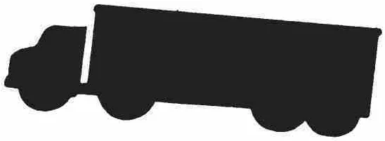 |
Heavy-duty truck (dual rear wheels) Rear axle load 142.3 kN (about 14.5 t), distributed over 2 wheels per axle including 30% impact |
92.5 kN | H-20 | 508 mm | 508 + 2s |
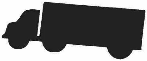 |
Medium truck (dual rear wheels) Rear axle load 106.8 kN (about 10.9 t), distributed over 2 wheels per axle including 30% impact |
69.4 kN | H-15 | 381 mm | 381 + 2s |
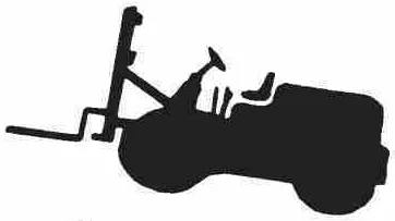 |
Forklift (rated capacity 4.5 t) Total machine weight about 11.1 t (with load), drive axle carries 85%, pneumatic rubber tires |
60.0 kN | 5 t class | 279 mm | 279 + 2s |
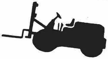 |
Forklift (rated capacity 2.7 t) Total machine weight about 7.2 t (with load), drive axle carries 85%, pneumatic rubber tires |
38.8 kN | 3 t class | 178 mm | 178 + 2s |
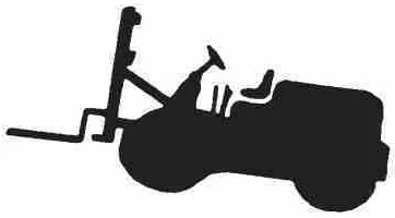 |
Forklift (rated capacity 0.9 t) Total machine weight about 2.8 t (with load), drive axle carries 85%, pneumatic rubber tires |
15.2 kN | 1 t class | 102 mm | 102 + 2s |
Wheel load values: truck single wheel load = axle load ÷ 2 × 1.30 (including 30% impact); forklift single wheel load = drive axle load ÷ 2 × 1.30. In the distribution width b , the s is the bearing bar center pitch (mm).
The smaller the contact length a and the shorter the span, the higher the wheel pressure intensity distributed to a single bar. For the same panel, a lighter vehicle + a shorter span can sometimes be more unfavorable than a heavy vehicle on a long span. During selection, verify each vehicle class that may actually occur one by one, rather than calculating only once for the heaviest vehicle.
Hard wheels such as polyurethane and nylon wheels are strictly prohibited on open steel grating: hard wheels have extremely small contact areas, and wheel edges may wedge into grating openings, causing concentrated wheel loads and structural damage. Such vehicles should use solid cover plates or close-mesh grating instead.
05Load Distribution and Calculation Model
5.1How wheel pressure reaches the bars
Wheel Load P enters the grating through the tire contact area, with contact length a along the span. Perpendicular to the span, the load distributes via cross bars to bars on both sides by one bar pitch s, so the distribution width is taken as b = a + 2s. The bar at the center of the distribution width carries the largest load, which is:
5.2Calculation Model and Moment Formulas
Take the most heavily loaded central bar as a simply supported beam carrying the distributed load P1/a placed symmetrically at midspan over a distribution length of a. Two cases by the relation between contact length and span:
5.3Concentrated Load Case
When a concentrated load (equipment feet, blocks, etc.) acts on one point of the grating, the two adjacent bars each take half: P1 = P/2; moment and deflection are calculated as for a midspan concentrated load:
06Load Capacity Calculation Method
Selection and verification under wheel load conditions in three steps.
Wheel pressure distribution - determine the vehicle class, wheel load P and contact length a per Section 4, and calculate the single-bar load by Eq. (1):
b = a + 2s, P1 = P·s/b
Moment and selection - choose Eq. (2) or (3) by the relation between a and L to calculate moment M1; the required section modulus of a single bar:
S1,req = M1 / F (F = 137.9 MPa) Select bars so that the actual S1 = t·d²/6 ≥ S1,req.
Deflection verification - for vehicle wheel load conditions use Eq. (5), for concentrated loads use Eq. (4):
D = P1(2L³ − a²L + a³/4)96E·I1 ≤ L/400
P1 in N, lengths in mm, E = 2.0×10⁵ MPa, I1 in mm⁴, D in mm. This formula joins accurately for both a = L (full-span uniform) and a → 0 (midspan concentrated).
For two or more continuous spans, multiply the results of Eqs. (2), (3) and (5) (M1 and D) by the continuity factor 0.80 before verification.
6.1Example: 4.5 t forklift aisle, 1 m span
Given: 5 t class forklift (wheel load P = 60.0 kN, contact length a = 279 mm); candidate spec G755/30/100 - bar 75 mm × 10 mm, bar pitch s = 30 mm; simply supported clear span L = 1000 mm; carbon steel.
- Wheel pressure distribution: b = 279 + 2×30 = 339 mm; P1 = 60000 × 30 / 339 = 5310 N. Since a = 279 mm < L = 1000 mm, Case 2 applies.
- Moment and selection: M1 = 5310 × (0.25×1000 − 0.125×279) = 1.142×10⁶ N·mm; required S1 = 1.142×10⁶ / 137.9 = 8284 mm³; the 75×10 bar has actual S1 = 10 × 75² / 6 = 9375 mm³ ≥ 8284 mm³, strength satisfied (88% utilization).
- Deflection verification: I1 = 10 × 75³ / 12 = 3.516×10⁵ mm⁴; D = 5310 × (2×1000³ − 279²×1000 + 279³/4) / (96 × 2.0×10⁵ × 3.516×10⁵) = 1.52 mm ≤ L/400 = 2.5 mm, deflection satisfied.
G755/30/100 heavy-duty steel grating on a 1 m simply supported span can carry 5 t class forklifts (wheel load 60 kN), with 88% strength utilization and 1.52 mm deflection < 2.5 mm. If the aisle may also carry H-15 trucks, verify separately with wheel load 69.4 kN and a = 381 mm, and take the more unfavorable case.
07Wheel Load Selection Calculator
Automates wheel pressure distribution, moment selection and deflection verification per the three-step method in Section 6. Results are for selection reference; formal design should be verified against actual project conditions.
Load and Geometry Input
Calculation Results
08Selection and Detailing Requirements
8.1Selection Process
- Determine the most unfavorable vehicle class that may occur on the aisle (one of the five classes in Section 4, or converted from actual vehicles).
- Propose preliminary bar size and pitch, and verify by the three-step method for strengthandDeflection.
- Re-verify each remaining vehicle class that may occur in the aisle and let the most unfavorable condition govern the selection.
- Use the 0.80 factor to re-check continuous arrangements and finalize the span and specification.
8.2Detailing Requirements
- Bearing length: bearing width at each end not less than 1.5 times the bar height and not less than 50 mm; trench covers should have position restraints to prevent displacement or lifting.
- Fixing Method: for vehicle areas prefer welded fixing (fillet welds, with the zinc coating repaired after welding) or dedicated clamping devices; vehicular trench covers should be fixed at four corners or restrained on both sides.
- Anti-Slip: use serrated (anti-slip) bars in ramps, loading/unloading areas, etc.
- Lateral stability of bars: bar height should not exceed 15 times the thickness; tall bars (e.g., above 75×5) on large spans should be checked for lateral stability or I-type bars used.
- Cross bar requirements: for vehicular grating the cross bar pitch should not exceed 100 mm, to ensure load distribution and overall stiffness.
8.3Service Restrictions
Vehicles with hard wheels such as polyurethane, nylon or steel wheels must not run directly on open steel grating; forklifts must use pneumatic rubber tires.
Vehicles beyond the load classes in Section 4 (heavier axle loads, special tires, tracks, etc.) are outside this criterion's distribution parameters; calculate separately using actual tire contact size and wheel pressure, or contact the manufacturer for dedicated selection.
The L/400 deflection limit balances walking feel, fastener forces and compatible deformation of the grating frame. In vehicular areas, even with ample strength margin, deflection exceeding the limit calls for larger sections or shorter spans, not relaxed limits.
09Technical Support
Common questions on selection, calculation and corrosion protection, selected from the Anping Steel Grating Factory technical column.